Understanding CAT Ratings

Overvoltage Category
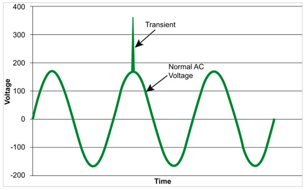
A voltage surge is a higher‐than‐normal voltage that temporarily exists on one or more power lines. Voltage surges vary in voltage amount and time present on the system. One type of voltage surge is a transient voltage. A transient voltage (voltage spike) is a temporary, undesirable voltage in an electrical circuit. Transient voltages typically last for a very short time, but they are large in magnitude and quite erratic. Transient voltages are caused by unfiltered electric equipment, lightning strike, capacitor bank, or generators being switched ON and OFF.
It is possible for transient voltages to reach several thousand volts. High transient voltages occur close to a lightning strike or when large loads are disconnected (see fig1). For example, when a large motor (100 HP) is turned OFF, a transient voltage moves down the power distribution system. When a test instrument or meter is connected to a point along the system in which a high transient voltage is present, an arc can be created inside the meter. An arc can lead to a high-current short in the electrical distribution system even after the original high transient voltage has gone. A high‐current short can turn into an arc blast.
When equipment is manufactured it may result in the selection and use of a number of voltages in its construction and supply. Some equipment may step a nominal voltage of 230 V AC down for safety considerations - such as SELV at 24 V for example. Whilst other equipment may step the voltage up into the HV (2.2 kV AC) territory (microwaves).
As required within BS EN 61140 Protection against electric shock – Common aspects for installation and equipment, the contacts in the position of isolation when new, clean and in dry conditions, shall withstand between the line and load terminals, the impulse withstand voltage given in BS EN 61140.
| Nominal voltage of the supply system V | Nominal voltage of the supply system V | Minimum impulse withstand voltage kV | Minimum impulse withstand voltage kV |
| Three-phase systems | Single-phase systems with middle point | Overvoltage Category III | Overvoltage Category IV |
| 230/400, 277/480 400/690 1000 | 120 - 240 | 3 5 8 10 | 5 8 10 15 |
Equipment forming part of the buildings installation, such as the metering, main distribution assembly and insulation material is permanently installed within the building. Unlike current-using equipment which is only powered up to turn itself on and off when it is used, the equipment forming part of the buildings installation is permanently connected to the electrical installation. This will require overvoltage protection.
Equipment energized directly from the mains supply
Technical committees shall specify the overvoltage category as based on the following general explanation of overvoltage categories:
- Equipment of overvoltage category IV is for use at the origin of the installation.
NOTE 1 Examples of such equipment are electricity meters, primary overcurrent protection devices and ripple control units. - Equipment of overvoltage category III is equipment in fixed installations and for cases where the reliability and the availability of the equipment is subject to special requirements.
NOTE 2 Examples of such equipment are switches in the fixed installation and equipment for industrial use with permanent connection to the fixed installation. - Equipment of overvoltage category II is energy-consuming equipment to be supplied from the fixed installation. If such equipment is subjected to special requirements with regard to reliability and availability, overvoltage category III applies.
NOTE 3 Examples of such equipment are appliances, portable tools and other household and similar loads. - Equipment with an impulse withstand voltage corresponding to overvoltage category I shall not have direct connection to a mains supply.
Measures shall be taken to ensure that the temporary overvoltages that could occur are sufficiently limited so that their peak value does not exceed the relevant rated impulse voltage in the table below.
NOTE 4 Unless the circuits are designed to take the temporary overvoltages into account, equipment of overvoltage category I cannot be directly connected to the mains supply.
| Three-phase | Single-phase | Voltage line to neutral | Overvoltage | Overvoltage | Overvoltage | Overvoltage |
| 50 | 330 | 500 | 800 | 1500 | ||
| 100 | 500 | 800 | 1500 | 2500 | ||
| 120 to 240 | 150 | 800 | 1500 | 2500 | 4000 | |
| 230/400 277/480 | 300 | 1500 | 2500 | 4000 | 6000 | |
| 400/690 | 600 | 2500 | 4000 | 6000 | 8000 | |
| 1000 | 1000 | 4000 | 6000 | 8000 | 12000 | |
| >1000 <1250 | 1250 | 4000 | 6000 | 8000 | 12000 | |
| >1250 <1500 | 1500 | 6000 | 8000 | 10000 | 15000 |
Measurement Category
Test instruments are temporarily introduced to become part of the electrical installation. As mentioned within overvoltage proteciton above, impulse withstand voltages are determined relative to equipments proximity to the source of supply for the electrical installation.
Measurement category is a way of classifying the terminals of test and measurement equipment according to the type of mains circuit to which they are intended to be connected. Measurement categories take into account:
- overvoltage categories
- short-circuit current levels
- the location in the building installation where the test or measurement is to be made
- forms of energy limitation/transient protection
Measurement category II
Applicable to test and measuring circuits connected directly to utilization points (socket outlets and similar points but excluding installed lighting) of the low voltage mains installation. Examples include measurements on mains circuits of household appliances, portable tools and similar equipment, and on the consumer side only of socketoutlets in the fixed installation. Short circuit currents are typically below 10kA, depending on the characteristics of the installation.
Measurement category III
Applicable to test and measuring circuits connected between Measurement category II and Measurement category IV of the building’s low-voltage mains installation. To avoid risks caused by the hazards arising from higher short-circuit currents, typically up to 50kA, depending on the characteristics of the installation, additional insulation and other provisions are required. For equipment that is part of a fixed installation, the fuse or circuit breaker of the installation must provide adequate protection against short-circuit currents.
Examples include measurements on distribution boards (including secondary meters), photovoltaic panels, circuit-breakers, cables, bus-bars, junction boxes, lighting, switches, wiring to socket-outlets, equipment for industrial use and some other equipment (such as stationary motors) with permanent connection to the fixed installation.
Measurement Category IV
Applicable to test and measuring circuits connected between the source of the building’s lowvoltage supply and the first accessible isolator switch able to disconnect all line and neutral connections. The high potential short-circuit currents, typically greater than 50kA, depending on the characteristics of the installation, existing in these circuits can create an extremely dangerous, high energy arc flash through any accidental short-circuit caused whilst making measurements. Precautions must be taken to avoid any chance of a short-circuit. Examples include measurements on the unisolated conductors at the isolator switch, the tariff meter, service fuse and low voltage devices installed in the sub-station.
Test instrument selection
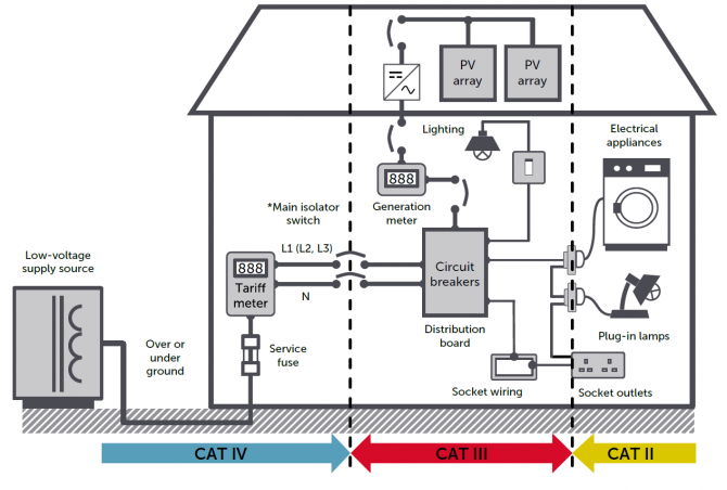
It is important when undertaking any measuring or tests on an electrical system to predetermine the proximity of the measurement position for the various parts of the building installation. Fig 2 illustrates the location of measurement categories with regards to the positioning within the buildings instalaltion.
The safety standard for test and measurement equipment, BS EN 61010, requires that terminals are marked with the value of the rated voltage to earth and the applicable measurement category, often abbreviated to “CAT.” Measurement terminals can be safely connected to a measurement category lower than the marking on the terminals. The measurement terminals must never be connected to a circuit that exceeds the rated voltage or measurement category.
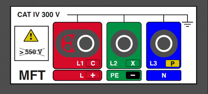
Figure 3 shows the marking on a typical multifunction tester. The tester is rated for CAT IV 300 V measurements. With this meter, measurements can be made to CAT IV, CAT III or CAT II circuits provided the voltage does not exceed 300 V to earth.
The 550 V indicates that measurements can be made between live conductors that do not exceed 550 V between phases.
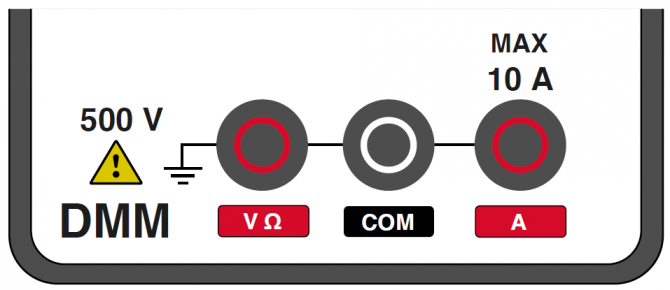
Figure 4 shows marking on a multimeter indicating it is rated for measurement connections up to 500 V with respect to earth.
However, as there is no specific CAT rating to this instrument it must NOT be used in connection to the mains supply as there is no declared overvoltage protection, even though it is rated to a greater voltage than the typical domestic supply.
Instruments and test leads without CAT ratings must have additional warnings in their instructions to limit their use, but this is often overlooked by manufacturers.
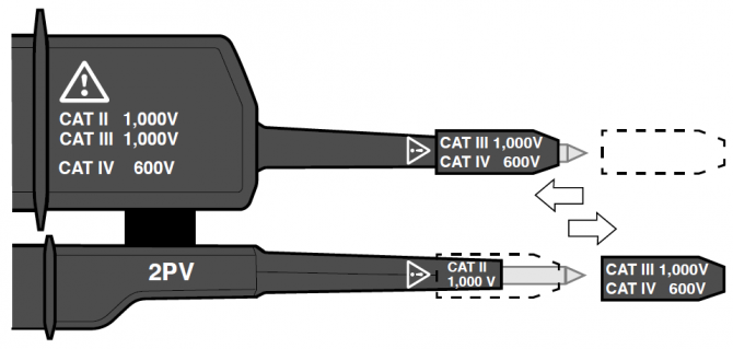
Figure 5 is a two pole voltage indicator. This is rated for measurment connection to CAT II 1000 V, CAT III 1000 V and CAT IV 600 V. This is achieved with combination of additional tips and insulators. With only a small tip exposd it significantly reduces the risk of short-circuiting between conductors, meaning it is safe to use in higher energy CAT III and CAT IV when installed. Further reading on electrical test equipment can be found in the HSE guide GS38: Electrical test equipment for use by electricians