Circuit Breaker ambient temperature and grouping
Ambient temperatures and grouping considerations for circuit breakers
When designing circuits often our main focus is to look at cable selection, paying attention to design current (Ib), nominal protective device rating (In) and the selected cables current carrying capacity (Iz).
We are told in Regulation 433.1 to maintain coordination between the conductors in the circuit and the protective device in that Ib < In < Iz.
Within BS7671 we apply a number of factors in this process to consider numerous varying design considerations such as ambient temperature, circuit grouping and buried cables.
However in this process on training courses we are instructed to select the protective devices with little other instruction, so these are often taken at face value. We assume 16 Amps means 16 Amps and 32 Amps means 32 Amps for example.
But let's look a little closer...
Regulations 134.1.1 states:
Good workmanship by one or more skilled or instructed persons and proper material shall be used in the erection of the electrical installation. The installation of electrical equipment shall take account of manufacturers' instructions.
Now you may consider manufacturers' instructions just to be the information contained within the equipment packaging, unfortunately this is just not the case and we need to visit the manufacturers' other literature either online or in publications to access full instruction and wider requirements to comply with BS 7671.
The temperature derating of miniature circuit breakers is an example of this.
BS EN 60898 and BS EN 61009 protective devices work on both electromagnetic and thermal loading conditions. Electromagnetic for high faults currents and thermal loading conditions for overload protection.
For a manufacturer to specify that a particular protective device is rated at 'x' Amperes nominal rating, it would need to be determined that this 'x' value is designed and calibrated to carry their rated current and to operate within their designated thermal time and current limits. If a device is installed at a higher or lower ambient temperature, then adjustments should be made to accurately understand the protective devices operational requirements.
For example
Hager provide a general catalogue for download and within this document is the more accurate information required to determine the temperature derating for their miniature circuit breakers. The following tables is sampled from the document:
| In (A) | -10°C | 0°C | 10°C | 20°C | 30°C | 40°C | 50°C |
|---|---|---|---|---|---|---|---|
| 6 | 7.92 | 7.44 | 6.96 | 6.48 | 6 | 5.52 | 5.04 |
| 16 | 21.1 | 19.8 | 18.6 | 17.3 | 16 | 14.7 | 13.4 |
| 20 | 26.4 | 24.8 | 23.2 | 21.6 | 20 | 18.4 | 16.8 |
| 32 | 42.2 | 39.7 | 37.1 | 34.6 | 32 | 29.4 | 26.9 |
| 40 | 52.8 | 49.6 | 46.4 | 43.2 | 40 | 36.8 | 33.6 |
| 63 | - | - | - | - | 63 | 58 | 52.9 |
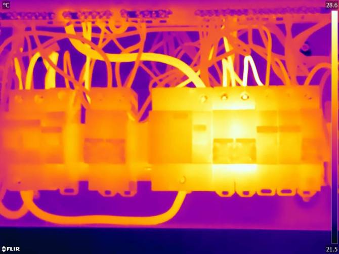
This image shows the impact of thermal loading onto adjacent protective devices.

It's important in an electrical design and subsequent inspection and testing practices that we take onboard full consideration of the manufacturers requirements.
This will often mean working beyond BS 7671 and researching these protective devices after inspection to make suitable observations based on accurate resource and information.
