Diverted Neutral Currents

The following is an article authored by both Rupert van der Post and Benson Fox from Tangle tamers electrical engineers ltd. The documents reference is: "Diverted Neutrals - some notes on TN-C-S supplies" R van der Post and B Fox –
Feb 2021 - ref TN-C-S-DN-1-RD-V1.6.
The work was done in callaboration with the e5 group.
DISCLAIMER
These background notes contain various information and opinions based on events and facts investigated. As with engineering judgement, ‘opinions’ are formulated based upon a review of the available evidence at a certain time and specific location.
The background information is general in nature, indicating tendencies we have observed on various sites. We have taken all reasonable steps and exercised due care and attention while compiling these items. However, errors can happen, and specific equipment and circumstances can change outcomes significantly. Therefore care should be exercised before designing or basing decisions on these items without further expert input.
SUMMARY
We (Tangle Tamers Electrical Engineers Ltd) undertake varied work, much of it on buildings which contain equipment and processes which are sensitive to magnetic fields and particularly to changes in magnetic field. Such buildings include:
- Electron microscopy and spectroscopy facilities
- Secure data centres
- Recording studios
- Medical imaging locations
- EMI / RFI screened rooms
Over the years, we have developed our knowledge and understanding of the causes of noise and interference issues which can give these installations and equipment problems. We are particularly interested in low frequency noise and interference.
If currents flow in an installation's earthing and bonding network or its metallic structures, they can generate significant magnetic fields. The fields generated by currents flowing in these elements are not cancelled by fields from return conductors sitting right beside them. So their local magnetic fields are strong and this causes problems.
Electricians are familiar with earth leakage, also known as residual currents, caused by high leakage plant and equipment such as rectifiers or inverter drives. A single item may generate anywhere from a few milliamps to many amps to earth. There is however, a lesser known phenomenon called Diverted Neutral Current (DNC) which can also cause current to flow in an installation’s earth network.
In an installation, a single TN-C-S supply to a building can give rise to diverted neutral currents that flow from the main earth terminal via bonding to extraneous-conductive-parts to the mass of earth (the “mud”). TN-C-S was also historically known as PME (Protective Multiple Earthing) - a common historic term – for a more detailed discussion of types of supply system earthing see section 312.2 of BS 7671:2018. Diverted neutral currents also can happen where two or more TN-C-S supplies have their CNEs (Combined Neutral Earth conductors) connected in any way.
For example, think about a steel frame building. That building is split into two halves each with its own theoretically-separate installation, each with its own TN-C-S supply.
However, BS 7671 (regulation 411.3.1.2 in the 18th edition 2018) requires that:
“in each installation main bonding protective conductors complying with Chapter 54 shall connect to the main earthing terminal extraneous-conductive-parts including
- Water installation pipes
- Gas installation pipes
- other installation pipework and ducting
- Central heating and air conditioning systems
- exposed metallic structural parts of the building”.
Therefore to comply with BS 7671 each installation must have the steel frame, services and lightning protection bonded to its own main earth terminal. This creates a common connection between the two TN-C-S supplies, where neutral current from the supply head in one installation can flow (for example) through the building frame or shared service connections, to the second TN-C-S supply head and vice versa. A simplified similar situation is described with a drawing on page 10 in this document, titled Scenario 2 - two interconnected TN-C-S supplies with a local load.
TN-C-S supplies can cause diverted neutral currents to flow in installation earthing and bonding networks. From there, the structures and services can then end up carrying diverted neutral currents when the supplies are not individually separated in stand-alone buildings. Also, some limited diverted neutral currents flow through the mass of earth (soil can be quite resistive).
It is not sufficient just to make the final cable drops to installations using separate CPCs. Similarly, it is not enough to just make a single supply truly TN-S (even properly, all the way back to the substation), when there are also TN-C-S supplies in the area or in that shared building. Diverted neutral currents can flow in something other than the neutral conductors. These currents can cause problems, hazards and danger, particularly when a DNO CNE connection is lost or broken.
REC/DNO/DSO regulations and practice
The regional electricity companies and distribution network operators commonly have rules or guidance which try to stop TN-C-S supply heads being connected together by low resistance earthing systems – e.g. avoiding multiple TN-C-S supplies being run into a common steel framed building, where each one
would be correctly connected, earthed and bonded to the requirements of BS7671.
For example, Western Power Distribution’s document SD5C/2 (2017) states:
4.5.3 New (and replacement) incoming cables to multi-occupancy buildings shall be Separate Neutral and Earth (SNE) type.
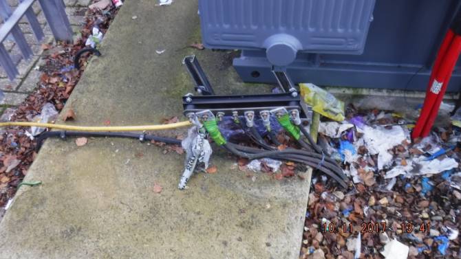
However, it is very common in older buildings to see multiple CNE (Combined Neutral-Earth) supply cables right into the building. Furthermore, the REC/DNO/DSOs do not always abide by their own rules. Illustration 2 shows just one recent example we have found of multiple TN-C-S supplies installed in the same building.
Earth and protective conductor currents from TN-C-S
TN-C-S supplies have many regulations surrounding them in BS7671. They are associated with an underlying risk of neutral currents flowing in the earthing system of a single installation from the "earth" or (more realistically and using a less confusing word) the "mud" outside an installation.
The wiring regulations aim to ensure that an installation is ideally an intact single equipotential zone and that the earthing and bonding conductors have cross sectional areas which are sufficient to safely carry their currents under normal operation and fault conditions.
In “good” modern 3-phase systems neutral currents are often still big. Even where phase currents are perfectly balanced, the sum of the triplen harmonic currents appears on the neutral. The Regs acknowledges that neutrals may even need to be bigger than the phase conductors on occasion to accommodate this. However, the Regs allow a default choice of protective conductors that have a much smaller cross section than the phase conductors.
The arrival of section 607 in the 16th edition of BS7671 (“EARTHING REQUIREMENTS FOR THE INSTALLATION OF EQUIPMENT HAVING HIGH EARTH LEAKAGE CURRENTS” - and its successors) shows that protective conductors are expected to carry some current in various “normal” operating conditions. However, little is said in the Regs about up-sizing protective conductors for significant
standing currents. The implication is that protective conductor currents are expected to be small, at least relative to the protective conductor size and capacity. When diverted neutral currents are added to the mix, this is not always true, and protective conductors should be sized appropriately for their standing currents as well as for any fault currents they may have to carry.
Secondarily, the Regs aim to ensure that the “earth” of a (TN-C-S) equipotential zone cannot readily be taken to outside locations where it might give danger (via the feed to a caravan, for example), without appropriate precautions. Where the earthing arrangements of multiple TN-C-S installations are crossconnected
(whether correctly or even inadvertently) the problem becomes difficult: parallel neutral paths are created through the earthing networks and the neutral current splits between the REC/DNO neutral path and the installations’ earth paths.
Many locations with multiple TN-C-S supplies interconnect them at least by the arrangement of the services, and by the bonding (even in brick buildings, and as the Regs require).
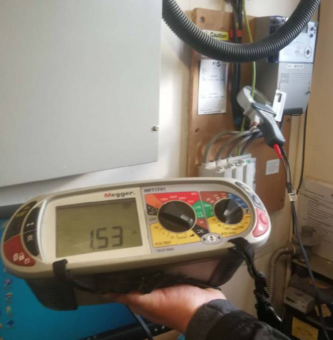
Illustration 3 shows a current measurement on the earth conductor in a business unit which is a laboratory. The current was low on the day the photograph was taken – historically we have seen over 5 Amps here sometimes. In this unit, the water system is bonded to the TN-C-S head via the main earth conductor and the main earth terminal.
The building’s water system is also bonded to other TN-C-S supply heads in a number of other units and in the shared common area of the building. This is a 1920s brick building but, even without a steel frame, we still find very significant currents flowing from supply head to supply head via the services and the bonding. The currents here are high enough that their magnetic fields ruin some types of
measurements in this laboratory.
As another example, we worked on a building that contained a large number of small recording studios, which had 3 separate TN-C-S supply heads within the building. The protective conductor system was carrying over 25 Amps diverted neutral current flowing from supply head to supply head when we measured it, due to this supply configuration. Because the earth currents generated strong magnetic
fields, electric guitars could not be used in some of the studios.
This shows that the interpretations of the definitions of multi occupancy are not being followed properly (or even listened to, sometimes – in the last example, one of the supply heads fed a bunch of new flats above the studio complex...).
Note that a separate earth entering the premises is not sufficient on its own. The local REC/DNO network, behind the final drop cables to the premises, may still be TN-C. The RECs often claim that an SNE (separate neutral and earth) cable entering the premises gives the premises TN-S.
This is not so. Consider if that premises has an SNE cable which connects to a CNE (common neutral and earth) cable in the street. Say the next-door unit in the same building also has an SNE cable to the CNE cable, connected to a different point on the CNE cable. Neutral current flowing through the CNE outer layer of the cable faces a parallel path through the 2 installations, if the systems, services, frame, lightning protection systems or other extraneous-conductive-parts of the 2 units interconnect to each other in any way.
This sharing of currents via parallel paths continues while the various supply heads are connected correctly. However, if the CNE conductor of one or more supplies breaks, the sharing path becomes the path for all the neutral current which would otherwise have gone along the failed conductor. Thus the sharing path can also become the path for load and fault currents, when it has already been carrying an excessive standing current.
SNE, TN-S, CNE, TN-C-S...
Using an SNE cable to a premises connects the customer's installation earth and neutral with separate conductors at the customer's installation. It does not guarantee to connect the other end to separate cable cores back to the substation star point and earth. It also gives no guarantee about the other installations in a multi-occupancy building.
The utilities routinely install CNE-cabled TN-C networks, almost by default. However, using combined neutral earth conductor cable within the wiring of the installation itself is regarded as a major defect and a very significant issue. Mud and concrete are resistive, they are not good insulators.
It has however become quite common practice for REC/DNOs to give an SNE final connection that goes back into the road: this then often joins on to a CNE (3-phase, 3 core + CNE armour) cable and carries on that way back to the substation.
In our opinion, this is not TN-S. TN-S is a separated Neutral and Earth all the way back to the substation. Take a look at the drawing - Fig 3.8 “TN-S system” in the Regs, in 312.2.1.1 “Single source systems”. The separation of the cpc and neutral goes all the way back to the transformer, not just to an arbitrary point a few metres outside an installation.
If the separation is not maintained all the way back to the source of supply for all the installations, then when those installations' Earthing networks or bonded metalwork connect, you have a possible neutral path via the earths. That path is in parallel with a length of the outer sheath / armour / CNE conductor of the DNO's cabling. The current flowing in each path is then determined primarily by the load on the distribution network and the relative impedances of the two paths.
Finally, for now, it may be interesting for the reader to contemplate TN-C-S supplies in multiple earthcoupled installations, and to then consider what happens when the DNO CNE conductor breaks outside the installation(s).
Here is a discussion on the subject: