Changes to RCD testing in BS 7671:2018 (2022)

One of the major changes to inspection and testing in Amendment 2 of the 18th edition is the changes to RCD testing.
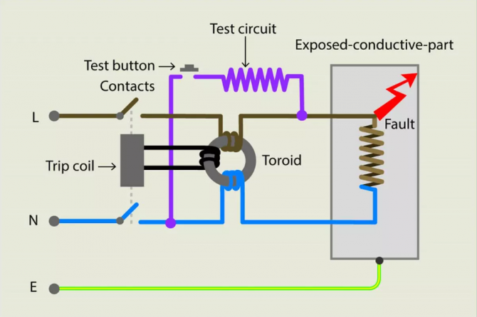
An RCD monitors the earth leakage current in a circuit. It is constructed from coils of wire wound around a ferrite toroid core, one for each live conductor of the circuit protected. When a current imbalance between live conductors is detected, a voltage will be induced in the tripping coil which will disconnect the electrical supply to the protected circuit.
Extract from BS 7671:2018 (2022)
“531.3.3 Types of RCD
Different types of RCD exist, depending on their behaviour in the presence of DC components and frequencies. The appropriate RCD shall be selected from the following:
(i) RCD Type AC: RCD tripping on alternating sinusoidal residual current, suddenly applied or smoothlyincreasing
(ii) RCD Type A: RCD tripping on alternating sinusoidal residual current and on residual pulsating direct current, suddenly applied or smoothly increasing.
NOTE 1: For RCD Type A, tripping is achieved for residual pulsating direct currents superimposed on a smooth directcurrent up to 6 mA.
(iii) RCD Type F: RCD for which tripping is achieved as for Type A and in addition:
(a) for composite residual currents, whether suddenly applied or slowly rising, intended for circuit supplied between line and neutral or line and earthed middle conductor
(b) for residual pulsating direct currents superimposed on smooth direct current.
NOTE 2: For RCD Type F, tripping is achieved for residual pulsating direct currents superimposed on a smooth directcurrent up to 10 mA.
(iv) RCD Type B: RCD for which tripping is achieved as for Type F and in addition:
(a) for residual sinusoidal alternating currents up to 1 kHz
(b) for residual alternating currents superimposed on a smooth direct current
(c) for residual pulsating direct currents superimposed on a smooth direct current
(d) for residual pulsating rectified direct current which results from two or more phases
(e) for residual smooth direct currents, whether suddenly applied or slowly increased, independent of polarity.
NOTE 3: For RCD Type B, tripping is achieved for residual pulsating direct currents superimposed on a smooth direct current up to 0.4 times the rated residual current (IΔn) or 10 mA, whichever is the highest value.
RCD Type AC shall only be used to serve fixed equipment, where it is known that the laod current contains no DC components.
NOTE 1: Examples of fixed equipment with a load current containing no DC componenets can include but not be limited to electric heating appliances and/or simple filiament lighting, neither containing electronic components.
NOTE 2: For guidance on the correct use of RCDs for household and similar use, see PD IEC/TR 62350.
NOTE 3: Some typical fault currents in circuits comprising semiconductors are given in Annex A53, Figure A53.1.”
Over the past few years I have tried to raise awareness of the changes in equipment and RCD technology.
In Amendment 2 of the 18th edition a much overdue change came through, suggesting limitations to the usefullness of Type AC RCDs.
RCD Type AC shall only be used to serve fixed equipment, where it is known that the load current contains no DC components.
This has naturally resulted in a lot more selection of, and therefore RCD testing of Type A RCDs. But no further guidance on how to test Type A RCDs has actually being made available.
The legacy method for testing RCDs has always simply been to test the device at x1/2 and x1 IΔn, with x5 also being required where the device was selected for additional protection.
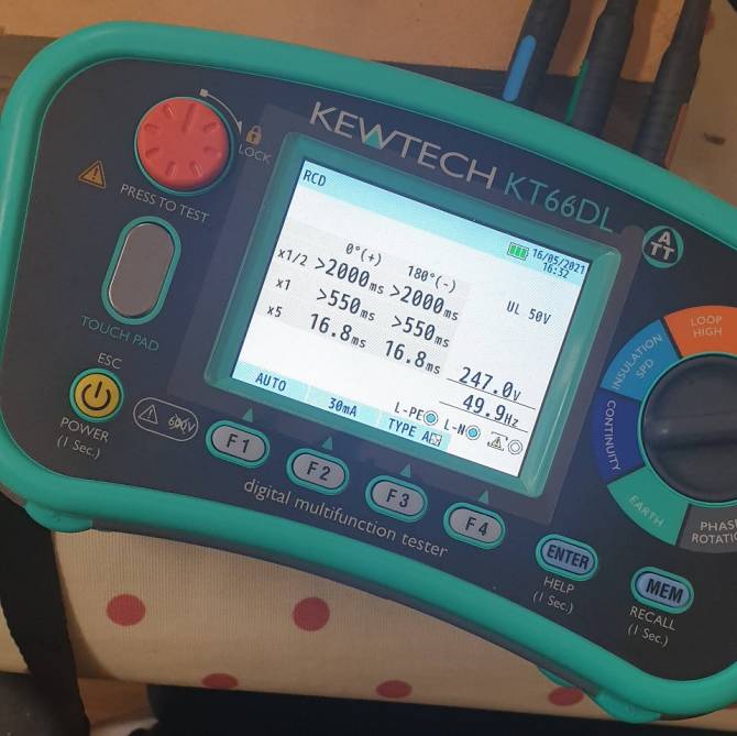
Some multifunction testers have introduced testing features for these various RCD types in their most recent models, with this legacy approach in mind, including the Megger 1741 and the Kewtech KT66DL.
But the question is why were RCDs tests like these carried out? and is it benefitial to test alternative type RCDs in the same way?
RCD Test instruments
RCD testers are manufactured to carry out the tests under the requirements given in BS EN 61557-6 Electrical Safety in Low Voltage Distribution Systems Up To 1000 V AC and 1500 V DC - Equipment For Testing, Measuring Or Monitoring Of Protective Measures - Part 6: Effectiveness of residsual current devices (RCD) in TT, TN and IT systems.

It is not the purpose of BS EN 61557-6 to verify the RCD works according to their product standards. This comes under standards such as BS EN 61008 or BS EN 61009.
BS EN 61557-6 specifies the requirements applicable to measuring equipment for testing the effectiveness of protective measures of residual current devices (RCD) installed in TT, TN and IT systems.
It includes the operating functions for the test instrument including:
- Measurement of trip current
- Non-tripping functions
- Fault voltage indication
- Measurement of trip time
Plus an annex detailing applicable tripping tests for different types of RCDs:
| RCD type | AC sinusoidal test current | AC half wave test current (pulsating direct test current) | Rising smooth direct test current |
|---|---|---|---|
| AC | X | n/a | n/a |
| A | x | x | n/a |
| F | x | x | n/a |
| B | x | x | x |
| B+ | x | x | x |
Why do we do RCD tests?
As the table and quote above demonstrates, all types of RCD must be able to detect Type AC fault currents.
The AC test is there to verify that the RCD tripping mechanism is functional and that it is not faulty or damaged by the logistics of wholesale or the conditions of installation.
Product standards such as BS EN 61008-1:2012+A12:2017 Residual current operated circuit-breakers without integral overcurrent protection for household and similar uses (RCCBs) Part 1: General rules includes the testing requirements for the manufacturer of the devices.
This will include:
- RCCBs having an IΔn > 0.010 A being subjected to 2000 operating cycles, each consisting of a closing operation followed by an opening operation. Operation will be as for normal use and consist of:
- the first 1000 operating cyucles by using manual operating means
- the following 500 operating cycles by using a test device
- the last 500 operatin cycles by passing through one pole of the residual operating current value IΔn.
- verification of the behaviour of the RCCB under short-circuit conditions
- verification of the risistance to mechanical shock and impact
- test of resistance to heat
- test of resistance to abnormal heat and to fire
- verification of the trip-free mechanism
- verification of the operation of the test device at the limits of rated voltage
- verification of the behaviour of RCCBs functionality dependent on line voltage
- verification of limiting values of the non-operating current under overcurrent conditions
- verification of behaviour of RCCBs in case of current surges caused by impulse voltages
- verification of resistance of the insulation against an impulse voltage
- Type A residual current devices
- verification of reliability
- verification of ageing
- electromagnetic compatibility (EMC)
- test of resistance to rusting
So how is this going to work?
Ok so we know a couple of things:
- Type AC RCDs are now becoming a less reliable device
- RCD tester standards (BS EN 61557-6) identify the different types of RCD and the disconnection requirements given in the product standard (BS EN 61008)
- RCD product standard states that the testing shall be carried out with the load disconnected
- AC leakage currents can occur from normal operation with no faults present in the circuit. Therefore we can use the AC test setting to verify the sensitivty of all RCDs as they all operate on sinusoidal AC residual current
- As the product standards require the loads to be disconnected, any electrical equipment which would provide DC residual current would not be connected within the circuit - therefore this residual current couldn't be exposed to a test and comply with BS EN 61557-6.
So moving forward the recommendation is to just test on the Type AC setting at x1/2 and x1 IΔn. The device shouldn't trip on the x1/2 and should trip within 300 ms on the x1 for a device to BS EN 61008 or BS EN 61009.
Further testing for fault finding or specific manufacturer requirements can be used, but these are not a requirement from BS 7671 and it should be observed that the IET Guidance Note 3 now comments on the excessive use of the operating cycle if done unnecessarily.
Since RCDs are only rated for a finite number of operations, carrying out frequent optional tests can shorten the product’s life. For example, in carrying out all of the above tests, including optional tests, for a 30 mA Type B RCD, would require the RCD to trip 12 times.